What should be understood about ink filtration
Filtering is an important step in the ink manufacturing process, but experience tells us that simply because the supplier passes your ink through the filter does not mean you can skip the filtering in the system. Ink will change over time, and if not protected, these changes can have a destructive impact on your system. In this article, we discussed the role of filters in different types of ink supply and provided suggestions on how to ensure that you choose the right filter and place it in the right position.
What is available?
There are many different types of filters to choose from. Perhaps the simplest is the type of woven metal mesh directly cut from the woven fabric. The particle size allowed by the filter is determined by the size (specification) of the metal wire and the number of overlapping grid layers. Filters are usually specified by the grid count, which is the number of openings per unit distance and is very similar to the printing resolution. The following figure shows how the woven cross lines define porosity and how to change the number of wire mesh to convert the effective particle size of the filter.
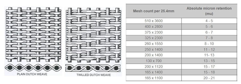
These filters can be welded into a stainless steel casing to form a filtering device. They have strong chemical compatibility and are very suitable for inks with strong acidity, high solubility, or high temperature. These types of filters perform very well in removing rough pollutants, but their relatively low surface area means they are more prone to clogging.
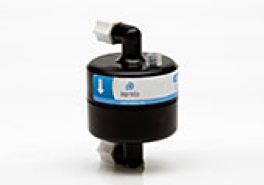
Currently, most inkjet printers on the market use polymer film filters. One variant is the capsule filter. Capsules are typically used as fill filters in ink systems, filtering the ink before it enters the system, or as recirculation filters (if the ink system does this, please refer to the schematic below). Like filters used in ink manufacturing, capsule filters are pleated to increase surface area and are multi-layered, allowing the filter to be used as long as possible before producing a significant decrease in flow.
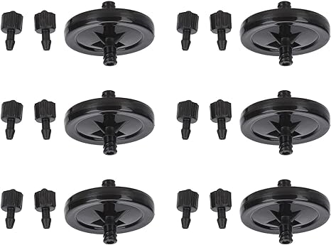
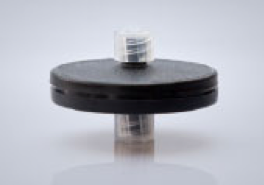
Another variant is the disc filter. The most common application of disc filters is the last chance filter (LCF), which is placed after the ink reservoir to filter the ink before it enters the print head. This is particularly suitable for multi pass printers with end shooter (non looping) print heads. These filters are also common in laboratory settings because they can be exchanged between different inks at a lower cost. Due to their ability to block quickly, they are not very common in recycling systems, although they are still sometimes used today.
Conclusion: Most inkjet printers use polymer film capsules or disc filters, depending on the amount of ink passing through them. In order to have higher durability at higher temperatures or stronger chemicals, metal mesh filters can be used instead.
Where do you put them?
In the following diagram, we focus on the locations where filters can be used in different types of ink systems in combination with end injectors and loop print heads.
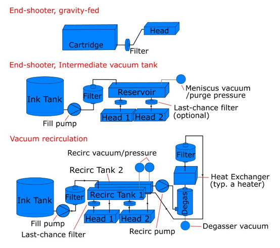
Since the main function of the filter is to ensure continuous cleaning of ink in the system, it should be placed in a location that captures any debris that may be generated by the interaction between ink and the system. In ink systems, especially when using UV cured ink, this often occurs after the heater and pump, which may lead to thermal and mechanical degradation of the ink. Cationic UV ink, such as ink commonly used for bonding metal and glass, is particularly sensitive to heat. The degassing module can also affect the reactivity of free radical UV ink, as reactivity may increase under anaerobic conditions.
It should be noted that filters provide necessary protection, but this cannot be achieved at the expense of sacrificing system performance. A potential issue is placing a filter near the print head entrance. The inkjet head itself is like an ink pump, sucking ink into the interior to refill, but has lower tolerance to inlet pressure fluctuations. Therefore, if they have to work very hard to suck ink through a clogged filter, they may experience a lack of pressure. One way to compensate for this is to place a pressure sensor between the print head and the filter to ensure that the pressure remains constant as the flow rate through the filter changes.
Conclusion: It is important to place the filter behind potential ink pressure points in the system, such as heaters, degassers, and even pumps, but remember that they can affect meniscus control by causing pressure drop at different flow rates.
Which aperture is suitable for me?
Some print heads include their own filters as part of the print head design. In the Seiko 508GS, Konica Minolta KM1024i, and Dimatix Samba print heads, metal mesh filters are integrated into the ink channels, while the Dimatix Q-Class and Ricoh MH series print heads themselves have perforated membranes in each ink channel. Choosing a filter size in ink supply is wise and can serve as the last line of defense for protecting nozzles and other built-in components, otherwise your nozzle lifespan may be affected.
For colored ink formulas, common fill filter sizes are 5-6 μ m. For dyes, 1um is sufficient. In the recycling system, using a 10um filter can extend the replacement interval and fully protect the nozzle. For white ink, particle deposition can cause clumping, resulting in clogging of the 10um filter, which may require a larger size filter. Special inks, such as metal sheets, may also have the problem of smaller filter apertures.
In some cases, it may be possible and/or desirable to use staged filtration time In this scheme, often used in ink manufacturing, the filling is stepped down 20um ->10um ->5um, for example Altough slightly costlier from a periodic service perspective, this approach can result in a reduced failure rate with time (and associated reliability) and still ultimately protect the head
Conclusion: Filters are used to protect the nozzle, so the smallest possible aperture should be used. At least, you should choose a size smaller than the nozzle diameter.
Filter malfunction detected
The position of the filter is a common cause of printing problems. As mentioned above, due to insufficient pressure on the meniscus, it may begin to lose pressure and the amount of ink droplets may decrease. Worse still, the nozzle may suck in air and stop spraying. Another common phenomenon is that the pump works too hard or for too long, making it difficult to refill the system in a timely manner; This indicates that your fill filter needs to be replaced.
Different issues depend on different system designs: what pump you are using and how they are driven. Pressure sensors can be used to monitor system characteristics and alert operators to error situations. Although this does increase the cost of the system, it is much better than sacrificing performance or letting the ink level surge inside the machine!
Finally, consideration should be given to the potential risks that filtering itself may pose to ink. In high fluidity applications, the shear force experienced by ink passing through the filter may be much higher than expected. Over time, the impact on ink stability may have unexpected effects. Before testing the customer, it is best to first test the system with the liquid to be used.
Conclusion: Filters can be easily added to prevent malfunctions in other parts of the system from damaging the print head, and do not assume that they are just attachments. They are still an integral part of the system that needs to be designed, monitored, and maintained.
Conversation with representatives
16th Building F2, Yuefu Avenue, Liangjiang New Area, Chongqing

© 2024 All rights reserved by Inkjet Research Institute. All rights reserved。渝ICP备2022008663号-1
