What is a waveform? After reading this article, you will have an understanding of waveforms
Want to further understand what waveforms are, how they work, and why they are essential components of your inkjet development? Because they are important but often not easy to understand. In this article, we will discuss the basic principles of waveforms, and in the next article, you will find practical steps to optimize waveforms for your ink. Starting from here, when you are ready to continue moving forward, learn how to optimize here.
basis
To help explain the purpose of the waveform, let's take a look inside the nozzle chamber of the print head. The following figure illustrates the injection process known as fill fire, which is typically applied to many different designs of print heads. In this case, a stack of piezoelectric ceramics (a type of piezoelectric ceramic material) will deform as long as a voltage is applied, changing the volume of the ink chamber, causing the ink to move within and ultimately spray out. The method of applying this voltage to piezoelectric ceramics is waveform.
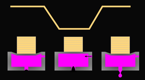
In our example, piezoelectric ceramics only elongate when a voltage is applied, so they do not deform before the print head is inserted. Once powered on, the print head maintains a specific voltage, allowing the piezoelectric ceramic to extend and remain in its non jetting position (left). If the voltage decreases, the piezoelectric ceramic retracts and expands in the chamber, drawing ink into the chamber (center). In order to spray ink droplets, the voltage returns to its original value, the ink chamber contracts, and the excess ink is squeezed out (right). This process repeats thousands of times per second.
It is important to note that the print head can be driven by positive or negative pulses, depending on how they are manufactured. Regardless of the way you are accustomed to looking at it, the important waveform timing is two tilted parts and a holding time, that is, the time for the voltage to remain at that level (high or low) before returning to the starting position. When the volume of the chamber returns to a stable state, the timing of this pulse determines what happens at the nozzle and is the first step to clarify when constructing the waveform.
Fundamentals of Pulse Timing
If you stand next to the print head while printing, you may hear it "sing", depending on the frequency of use. The reason you can hear it is because the actuator produces sound waves. For jetting, the most important ones are those generated within the ink itself, as they define the pressure changes that produce ink droplet jetting.
Due to the presence of ink with certain mechanical properties and the fact that sound waves lose energy when rebounding, the pressure inside the cavity can be described as a damping resonator. Any change in pressure, such as the deformation of piezoelectric ceramics, will lead to a change in characteristic pressure. As shown here, when the piezoelectric ceramic retracts and the chamber volume increases, the pressure change causes the ink to start moving back and forth in the chamber.
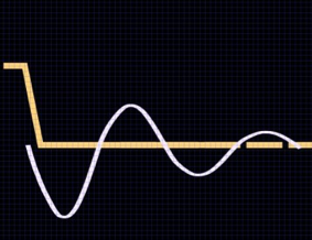
This energy itself is usually not enough to make the ink spray out, it only pulls the ink back to the other end of the chamber and then bounces away. By using voltage pulses at the correct time to enhance pressure, ink droplet spraying becomes more effective, as shown below. When the pressure exceeds the critical value, due to the optimal timing, ink droplets are sprayed out。
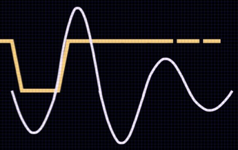
The reason why pulse width is so critical is that if it is too short or too long, the waves, pressure, and motion of piezoelectric ceramics will be asynchronous. If the ink does not move in the correct direction instead of steadily increasing momentum when adding more pressure, the momentum may be offset. Similar to pushing a child on a swing. If you push them at the right time, the momentum increases and they swing higher. If you push them at the wrong time, they will stop violence. Similarly, if the pulse width is incorrect, the injection generated repeatedly will be inefficient and unstable.
Due to the need for ink to move back and forth along the length direction of the pressure chamber, the maximum frequency that the print head can output depends on the size of the pressure chamber of the print head. In print heads with longer pressure chambers, it is not possible to spray droplets at high frequencies due to the time required for the reciprocating motion of sound waves.
Due to the fixed length of the nozzle cavity, you may assume that the pulse width required for correctly timing pressure waves for a given print head is constant. However, timing is also influenced by the speed of sound of specific ink. That's why it's necessary to adjust the waveform for specific ink and print head combinations, as having a universal waveform is not enough for that print head. Fortunately, if the ink properties are similar, the same waveform can be well applied to both.
What is resonance?
Usually, a waveform that works well at one frequency may not work well at another frequency. All of this is attributed to the pulse timing when the ink moves back and forth in the chamber. As the printing frequency increases, the waves and motion generated by a given pulse can begin to interact with the previous pulse. At certain frequencies, this will be enhanced, resulting in resonance, as seen in the example at the top of the image.
The higher the printing frequency, the greater the likelihood that the pressure has not decayed to zero before the next pressure drop and pressure wave occurs, thus increasing the likelihood of poor combustion. If the ink is still flowing, the previous pulse may increase pressure (higher speed, more satellites, wetting) or decrease pressure (lower speed). If your printing speed is flexible, it is wise to study the formation of ink droplets within a certain frequency range to ensure that your final printing speed does not fall within the frequency range where resonance occurs.

Multiple pulses
If electronic devices allow, then each pixel can use multiple pulses, allowing you to produce larger and faster ink droplets. The waveform of multiple pulses usually depends on the first or second resonance of the pressure wave. This means that when the ink moves towards the nozzle, the first pulse will increase the pressure on the ink. Some ink will spray out, while the rest will rebound from the spray hole and return to the opposite side. Once the ink flows back to the nozzle, the second pulse will increase its momentum. Pulses should be carefully tuned; Enhancement can be very strong, over driving pressure and generating nozzle wetting.
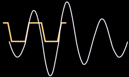
If the pulse amplitude is the same, the second droplet sprayed will be larger and faster than the first droplet because it is based on the resonance of the previous pulse. It can be merged on the panel or during flight, depending on several factors, including head design, pulse to pulse timing, voltage used, and ink properties.
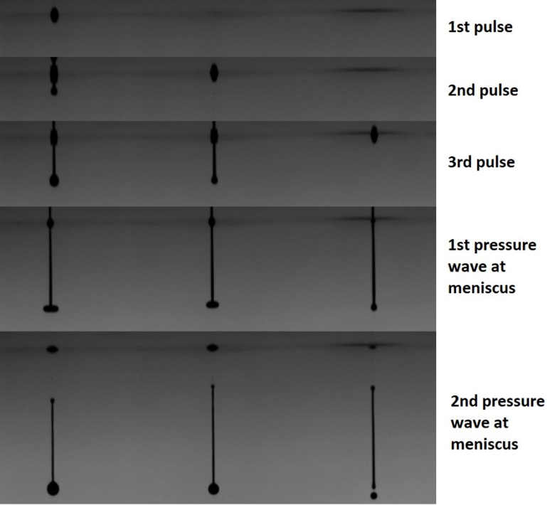
Being able to see the formation of ink droplets in real-time helps to understand these effects. In the photos taken with the JetXpert ink viewer below, you can see that water droplets of different sizes form in adjacent nozzles through resonant multi pulse waveforms. The left nozzle has three waveform pulses applied to it, the center nozzle only has the last two pulses, and the right nozzle only has the last pulse. The three pulses used to generate ink droplets are evenly spaced in time, and each image is taken when the pressure wave hits the nozzle opening.
Please note the extension of the nozzle meniscus after the pulse ends, which is caused by pressure waves. The first type even occurs before ligament separation. The meniscus protrusion on the nozzle that has been fired two or more times is larger, indicating that additional pressure has already been applied due to the previous pulse. By adjusting pulse time and visualizing your progress, you can improve the waveform of specific inks faster.
The additional pulse is not only used to spray larger ink droplets. Usually, a pre pulse on the "off" data is used to trigger the nozzle, which means providing sufficient force to keep the ink moving inside the nozzle without spraying ink droplets. Another application is to use post pulses to eliminate meniscus oscillations, allowing you to increase frequency without being disturbed by the previous drop. The waveform below has many built-in functions and is adapted from the Ricoh desktop printer patent.

Our introduction to waveforms ends here. Next, we will learn how to create waveforms from scratch or optimize existing waveforms for specific inks.

