The History and Differences of Piezoelectric Thermal Printing and Continuous Inkjet Printing
In this article, let's take a look at some of the original innovations that today's inkjet printing industry is based on, and how they have matured into three different technologies: piezoelectric, thermal, and continuous inkjet printing. The main purpose is to gain some historical perspectives and familiarize oneself with the language used, explore some differences between the three technologies, and may guide you in choosing which technology is suitable for your application. Because we only love inkjet, it also gives us the opportunity to pay tribute to those who started this incredible journey。
Early inkjet technology emerged
Before the digital age, Elmqvist described one of the first "liquid jet" devices in a 1948 US patent application (US2566443A), from which the annotated accompanying drawings were copied and modified.
It is not capable of printing text or images, but forms an oscilloscope, a machine that records continuous changes (i.e. analog) measurements. Its working principle is that the pressurized liquid is squeezed through a thin tube, which is replaced by a current driven circular coil.
For history enthusiasts, it is interesting that this concept is not completely different from the famous ink siphon recorder patented by William Thomson (later Lord Kelvin) in 1858 (UK Patent 2147/1867).

The key to Elmqvist's patent is to increase the frequency of operations by avoiding contact with the recording surface, compared to previous direct ink writing. It is precisely this special advantage that makes the Elmqvist device the pioneer of the inkjet printer we will discuss next.
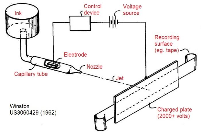
The first patented digital inkjet device was invented by Mr. Winston from Teletype. The device utilizes the principle of static electricity to generate continuous small jets, but can be opened and closed, with a response time of approximately 1ms. The following patent image provides a detailed description of the main components of the system. It uses fine glass capillaries, similar to Elmqvist's machines.
Continuous inkjet was born
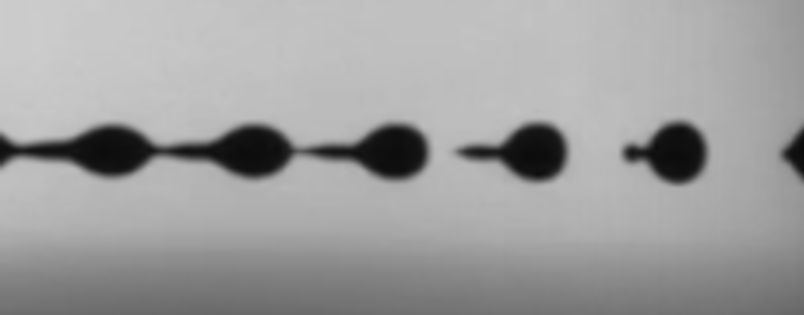
Let's go back to the late 1960s when the first version of inkjet equipment based on the principle of continuous inkjet (CIJ) emerged. As the name suggests, this method relies on pressurizing ink to form a continuous liquid flow, just like Elquist. The main difference this time is that through the action of sensors (or actuators), the airflow is divided into individual charged droplets. Sensors are devices that convert electrical signals into mechanical motion. This type of droplet breakage is shown in the figure below, recorded using the JetXpert system.
It is obvious that to achieve a controlled pattern, such as text characters, there is no need for some droplets. In CIJ, those that are unwanted are transferred by static electricity to a collection device (collector, sink), while those that are desired are allowed to impact the printed surface. This choice is achieved by charging the droplet as it passes through a set of electrodes and using a voltage of 1000 volts from another set of electrodes to push the droplet to the side. After unwanted ink droplets are pushed laterally into the slot, the ink is circulated back to the starting point for spraying again. From a design perspective, writing characters can be formed by transferring a single droplet flow to multiple locations (Lewis&Brown, USA 3298030) or creating parallel flows (Swift, USA 3373437), as shown in the patent image annotated below.
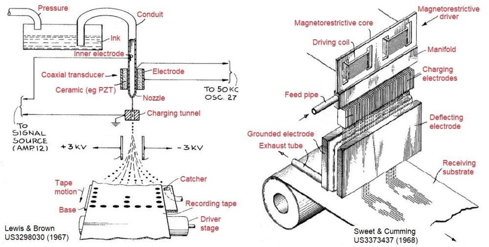
In Lewis and Brown's design, this was achieved by piezoelectric elements, which are made of ceramic lead zirconate titanate (lead [zirconium (x) titanium (1-x)] O3), piezoelectric ceramics) that deform when exposed to electricity. This deformation is caused by pressure modulation by squeezing glass fibers. In the array design of Sweet&Cumming, the actuator is described as magnetostrictive, which means that when magnetized, it will change its shape.
The development speed of CIJ technology is astonishing. By the early 1970s, the world's most famous computer companies, such as International Business Machines, Casio, Hitachi, and Xerox, were constantly inventing. Today, CIJ systems are one of the most commonly used types in industrial data encoding applications. This is largely due to the ability to carry useful polymers in strong solvents such as methyl ethyl ketone to produce fast drying ink. The faster the ink dries, the faster the printing speed - which makes CIJ popular in high-speed applications. This provides a key advantage in industrial applicability, especially when matched with the high reliability that CIJ printer developers are concerned about.
Due to the extremely low solid content, low boiling solvents (such as alcohol) can be effectively removed on high-speed production lines for food safety. Food packaging is another important market for CIJ. Printing the best date directly on perishable products, such as eggs, is just one example of many different places CIJ uses. To better compare different printing techniques, these techniques can be used to encode eggs or other products. Please refer to this article. This article
Due to its versatility and long throwing distance, CIJ continues to be applied in the 21st century. With the support of increasingly complex manufacturing methods, Kodak has developed the CIJ concept into one of the fastest color inkjet printing processes to meet the network speed requirements, such as newspaper printing. We will discuss CIJ and Kodak streaming technology in specific future posts.
On demand inkjet development
紧随最初的CIJ发明之后,研究人员正忙着创造喷墨设备的设计,这种设备通过使用电信号谨慎地产生液滴(仅在需要时)。这些打印头通常被归为按需喷墨。多年来,实施范围相当广泛,依靠各种物理过程来喷射液滴。目前使用的最常见类型依赖于突然局部加热(热喷墨)、用致动器挤压油墨(压电喷墨)或用机械阀释放加压油墨(阀喷射)。
一个关键的优点是减少了对加压和再循环墨水的需要,潜在地使墨水供应系统更简单。由于蒸发损失,也不太需要用溶剂定量来控制粘度。国防部喷墨的流体兼容性也更广,包括电绝缘材料。
Early arrival of piezoelectric magnetic heads
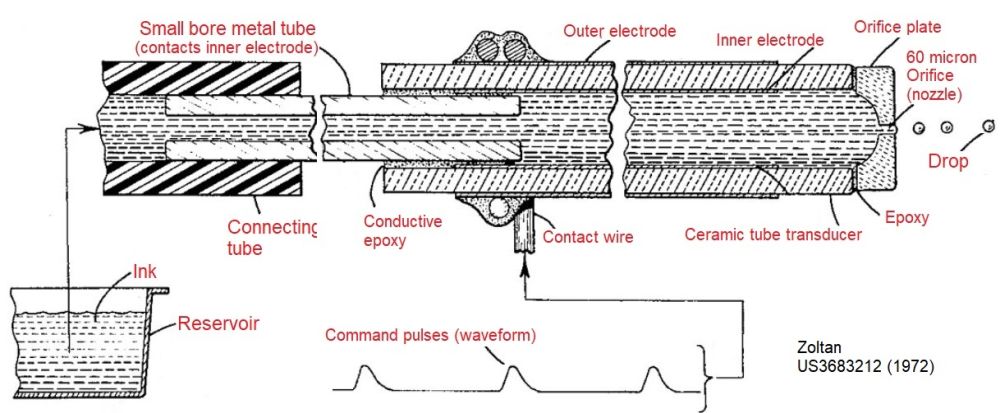
The first PIJ (Piezoelectric Inkjet) nozzle patent still available today was obtained by Zoltan in 1972, who worked at Clevite and Lewis&Brown, known for CIJ. Zoltan uses a single cylindrical PZT actuator, which is glued or wound around the end of a thin tube, just like their design. As shown in the figure below, if PZT is directly in contact with ink, it can operate without applying high voltage, but the patent mentions the possibility of ink corroding electrodes. Therefore, Zoltan has foreseen one of the biggest challenges in printhead design today, which is material compatibility. Detailed information on material compatibility will be introduced in the current printhead design section.
The main difference from CIJ is that the electrical signal of piezoelectric ceramics is only applied when it needs to fall. The disadvantage is that the ink droplets do not charge or deflect, so several actuators are needed to form a character printer. The use of multiple glass fibers to achieve this array is a theme of continuous invention (e.g., 4288799 in the United States, Canon), but as we will see next, there is a better method.
A few years later, the siloxane head described by Kaiser and Sears was the first publicly available design to use a planar shape (planar) driver to design a piezoelectric head. This is very important because it allows devices to be stacked together to form a character printer, as shown in the following figure. Of course, there is a certain limit to the distance between the nozzles, which depends on the layer thickness of all the parts used. Nevertheless, the principle of one-way printing has become possible, providing the greatest growth potential for industrial inkjet printing today。
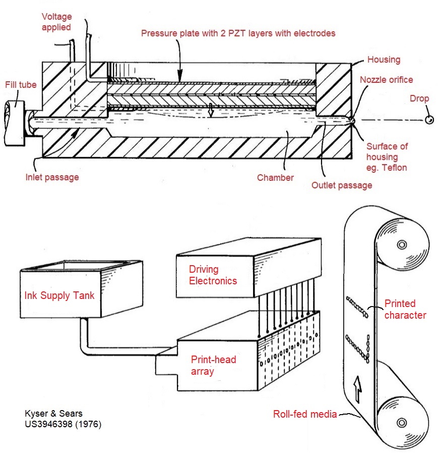
In fact, the Silonic design represents the direct ancestor of early print heads such as the Xaar and XJ500, which also used PZT's shear mode actuator, but achieved nozzle spacing at a smaller distance through more advanced ceramic processing and innovative shared wall drive solutions.
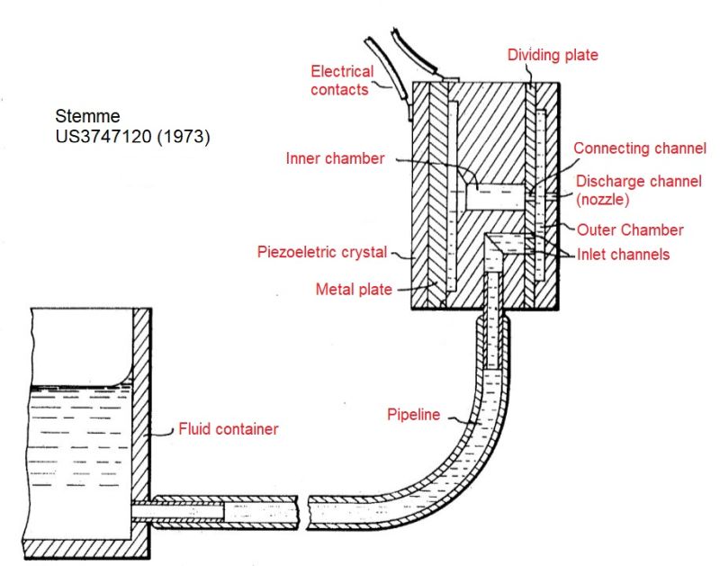
Stemme (authorized in 1973) solved the problem of increasing the number of nozzles with better spacing early on in his design. He described a series of "capillary injectors", each with a piezoelectric crystal to extrude ink. There are several groundbreaking reasons for Stemme's design: (1) it was the first patent to use "channel" and "chamber" language in monolithic (monolithic) designs, (2) like Silonics, it uses PZT in bending mode, but most importantly: (3) the jet is formed perpendicular to the PZT plane, thus creating the popular "roof" actuator structure in contemporary design. It even describes the shape of pulses or waveforms to control the possibility of air entering the nozzle, which is now a well-known fault mode。
Therefore, we have introduced some historical developments that support the principle of piezoelectric heads in the Ministry of National Defense. If you want to know what shear mode or roof mode means, don't worry, we will soon return to some details in a piezoelectric head specific post. We will also discuss more about the current print heads, which, due to their wide ink compatibility, support most of the industrial printing applications we see today, from transaction printing (billing) to large wooden boards used for flooring.
Hot bubble nozzles reduce costs
PIJ's main competitive technology came very late and was disclosed in two Canon patents published in 1981. Due to HP's dominant position, this principle is commonly referred to as Thermal Inkjet (TIJ) today, but Canon initially created the "Bubble Inkjet" brand because the heating mechanism causes cavitation (bubbles).
The principle of TIJ is that the increase in pressure near the nozzle is not caused by machinery, but by heat. Although laser is mentioned as a possible source in a patent, the most practical method is to use resistors. Physics tells us that for resistors, the power loss due to heat is proportional to the square of the current multiplied by the resistance. Therefore, a sufficiently high resistance and an appropriate amount of current can generate local heating very quickly. Referring to the left figure below, we can see how simple the principle is and how similar it is to the first PIJ design invented by Canon.
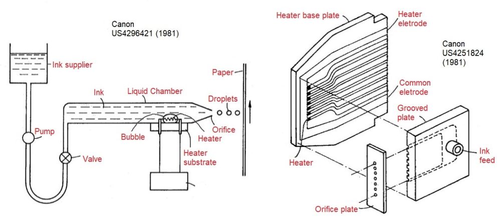
If you still remember the early 1980s, you will recall that personal computers became increasingly easy to use in offices and homes, driving the demand for "hard copy" printouts. This has driven the demand for economically efficient solutions. The difference in thermal print head technology is that it was designed from the beginning to have scalable micro manufacturing processes. The large-scale manufacturing processes already used in electronic devices, such as printed circuit boards and silicon wafers, may soon adapt to the manufacturing of TIJ magnetic heads. This in turn leads to lower unit costs during mass production. The right figure above shows the first example of using thin film circuit technology to create a nozzle linear array. Please note that the size of the heating pad is only 150 microns, which means the nozzle spacing is less than 1 millimeter.
It should also be emphasized at this point that, unlike the PIJ invention, it first uses a diluted version of existing ink/liquid, and the ink for the thermosensitive head is developed together with mechanical components, so it can work as a system. This is because the function of the heater depends on the specific mixture of solvents to be carefully selected and the solid content of the ink. As shown by observing the kettle, heating elements are easily contaminated! When we consider TIJ in more detail, we will reconsider this topic.
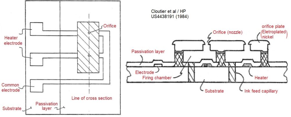
Around the same time as Canon, HP developed a competing thermal print head. The manufacturing of high-density injectors is also an important subject disclosed in the present invention, although the following figure only shows two nozzles. The claimed main step is to use standard techniques to manufacture the head into a single unit, thus avoiding the complex alignment process that may cause manufacturing errors.
In the next 30 years, HP, Canon, and most recently Memjet will continue to develop magnetic head manufacturing processes based on what is now known as silicon microelectromechanical systems. Using this approach, HP particularly hopes to lead industrial printing, using modular design and emphasizing printing systems that extend to the page range. We will come back to discuss in more detail what made this successful.
The value jet print head goes far beyond the scope of ink
When the printing volume needs to be larger and the point resolution of the printed pattern does not require such high accuracy, the valve jet device may be very useful. This technology is sometimes referred to as Mechanical Inkjet (MIJ).
Until the recent resurgence of ceramic tile manufacturing technology, large character encoding or high coverage textile printing, such as carpets, were the main uses. This type of print head typically uses pressurized ink supply, which is forced through a relatively large nozzle that is opened and closed by a mechanical actuator. Therefore, these devices act like a row of jet valves, whose output is either very large droplets or well oriented spray, depending on the design.
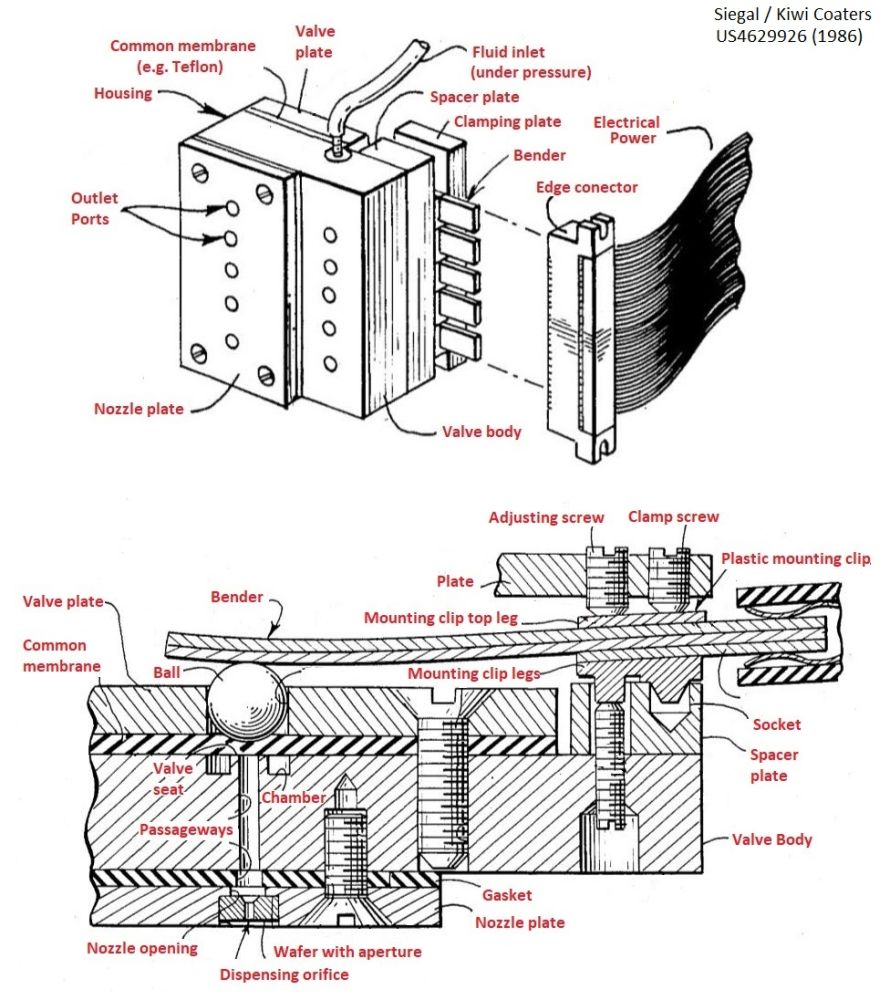
The following figure shows the early design of Valvejet, which was patented by American company Kiki Coders during the peak of inkjet growth in the mid-1980s. This design relies on a PZT actuator, which is bent to seal the ball bearing on a flat valve seat using PTFE film for reliable sealing. Considering mechanical differences, each channel can be tuned using adjustment screws.
Due to the large size of the parts, the printing frequency is usually much lower than the CIJ or other Ministry of Defense equipment we have already discussed, although dots are not often needed. ReaJet promotes their DOD 2.0 system to operate at an impressive speed of 600 meters per minute.
The main advantage of valve injectors is that they can deposit larger volumes of material and "eject" droplets over long distances due to their ability to apply high pressure. This means that these applications are truly industrial applications. For example, ReaJet describes trace amounts of oil on cosmetic applicators to make assembly easier.
The viscosity range is usually much wider than other inkjet printers, which is a major driving force for their use of high solid content inks such as ceramic glaze. However, due to the presence of such abrasive particles, reliability is attributed to the ability to reposition the valve after multiple drives, which led to continuous invention. We will discuss the application of ceramics, including the use of valve injectors, in another article.
summary
So now we have a feeling about how early printhead designers started. In the following post, we will revisit some examples and describe their designs, as well as how they match the expected application. For PIJ, this will include different geometric shapes and contemporary manufacturers (KM, Fuji, Xaar, etc.) as well as waveforms used to make them work. For new entrants of TIJ and other types of defense, such as MEMjet and Tonejet, they will also be included. As we mentioned earlier, we will soon see valve injectors.
Conversation with representatives
16th Building F2, Yuefu Avenue, Liangjiang New Area, Chongqing

© 2024 All rights reserved by Inkjet Research Institute. All rights reserved。渝ICP备2022008663号-1
